
Electrical circuits used for the robot are included below. We were able to space out the circuits across the bottom and top layers of the robot.
TIVA PinoutWe used the 20- and 24-pin ribbons of the TIVA Launchpad. Connections were determined according to reachability and alternate functions needed for each pin.
|

|
IR Sensor
IR Sensor circuit was used to detect IR emissions from the MINERs. We used two potentiometers on the two different gain stages of the IR detection circuit so that we can adjust the gain levels on field without having to rebuild the circuit. This proved to be very useful as we were able to adjust different sets of gains while testing with MINERs on the field. Capacitors were used throughout the power and ground to reduce noise. This circuit resulted in a consistent rising edge timing, with the duty cycle of the signal dependent upon our distance from the MINER.

Color Sensor
|
To detect our relative location in the field, we used TCS34725 Color sensor that was provided in the lab kit. The sensor was mounted on the bottom of the robot and calibrated on the field to provide optimized readings.
|

|
Accelerometer
|
We used the ADXL343 accelerometer to control our motors. It was mounted on the top layer of the robot right next to the magnets to ensure stability while getting effective collision readings.
|

|
Motor Drive train

|
The TLE 5206 driver was selected to control our two motors connected to each wheels. Two pins were used to control each of the motor drivers -- IN1 was a digital output set depending on direction of rotation while IN2 was connected to PWM signal from the TIVA to control the speed of the motor.
|
Synchronized Permitting and Usage Designator (SPUD)
|
SPUD was used to communicate about the status of the mining operations. It communicated with our robot over a 4-wire SPI bus, and was able to be recognized by and communicate wirelessly with the Peterson Pediment. Synchronized Permitting and Usage Designator (SPUD)
|

|
Power Distribution

|
We were provided with two 7.2 V batteries to drive the motors and power the boards. Two switches and a fuse was used to ensure safety. The motor drivers were powered by 14.4V while the TIVA was powered by 7.2V.
|
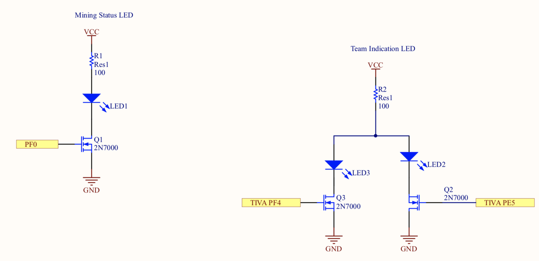
Indication LEDs
|
Clear visible indicators were required throughout the game. An LED was used to indicate the mining operation status by blinking. Our robot also utilized two LEDs to indicate which team the robot is playing on. The two LEDs that were used to indicate the robot's team was toggled with the button on the TIVA.
|
|
