
Overall Design Strategy
We decided to build our TRACTOR in two layers, with Duron structural support members providing strength to withstand impacts with other TRACTORs. 6-32 screws with T-slot nuts provided sufficient holding forces while also being removable during testing. For our wheelbase, we elected to use two drive wheels with a single ball caster on the back of the robot. Having 3 points of contact prevented any issues due to uneven terrain on the field, at the expense of the ability to turn about our central axis.
For grappling MINERs, we elected to use Neodymium (NdFeB) permanent magnets instead of the electromagnets that were used by all other teams. The holding force of an electromagnet is based on a flat steel plate, so we hypothesized that a single 2.5kg electromagnet would be unable to hold the MINER with sufficient force, and even the use of two electromagnets would require precise alignment with the MINER to engage. Permanent magnets, however, have higher field reach-out than electromagnets and can have comparable holding force with a reduced weight and volume footprint. As such, our strategy involved grappling both one of our team's MINERs and one of the other team's, after which we drove into the exclusive mining location for our team to both mine resources and take one of the other team's MINERs out of commission.
For grappling MINERs, we elected to use Neodymium (NdFeB) permanent magnets instead of the electromagnets that were used by all other teams. The holding force of an electromagnet is based on a flat steel plate, so we hypothesized that a single 2.5kg electromagnet would be unable to hold the MINER with sufficient force, and even the use of two electromagnets would require precise alignment with the MINER to engage. Permanent magnets, however, have higher field reach-out than electromagnets and can have comparable holding force with a reduced weight and volume footprint. As such, our strategy involved grappling both one of our team's MINERs and one of the other team's, after which we drove into the exclusive mining location for our team to both mine resources and take one of the other team's MINERs out of commission.

MINER Detection
To detect MINERs, we used the phototransistor circuit seen in our electrical design schematics. However, we needed to prevent the phototransistor from detecting MINERs that were not directly in front of our TRACTOR, thus causing misalignment. Therefore, we built an enclosure with a slit to ensure that the phototransistor only sampled IR light from a single plane in front of the TRACTOR.

MINER Detection Module
|

MINER Not Detected, Not Yet Aligned
|

MINER Detected! Drive Forward
|
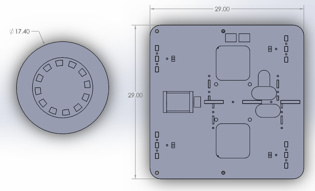
MINER Capture Dimensions
|
|
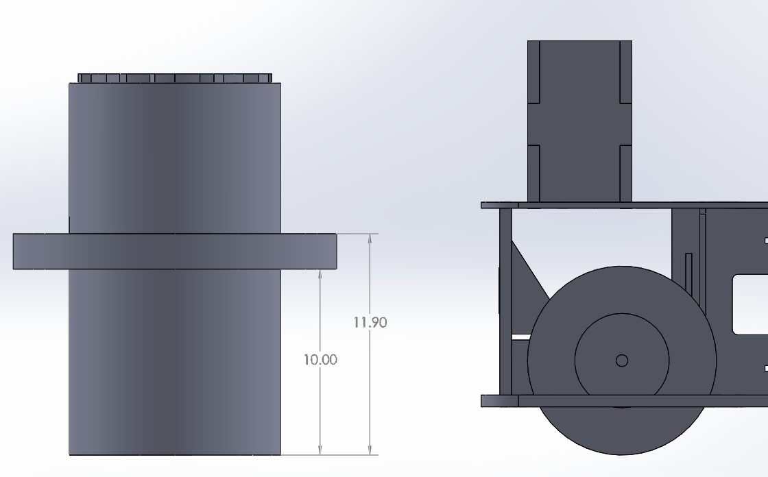
Driving Module
To drive our wheels, we attached the provided gear-motors to a drive shaft with a clamping shaft coupling. The shaft was singly supported with a flange bearing on the interior side of the wheel, which was sufficient to prevent damage to the motors and shaft bending during the testing period of the project. Encoders were mounted directly on the back of the motor by using a 3D printed mount with M2 screws directly screwed into the motor.


|
|
